
Pipe Flanges: The Simple Connection Behind Complex Piping Systems
If you are new to industrial piping, the word pipe flange may sound more complicated than it really is. At its simplest, a pipe flange is a mechanical component used to create a strong, detachable connection between pipes, valves, pumps, vessels, fittings, and other equipment. Instead of permanently welding every part of a piping system together, engineers can use flanges, bolts, and gaskets to create connections that can be opened whenever inspection, maintenance, replacement, or cleaning is required. Think of a flange as a carefully engineered doorway between two sections of a piping system: it allows the connection to be secure when closed but makes access possible when maintenance is needed. In industries such as oil and gas, petrochemical, chemical processing, power generation, fertilizers, pharmaceuticals, water treatment, and process engineering, this simple principle becomes extremely important because piping systems may carry fluids at high pressure, high temperature, or highly corrosive conditions. The flange therefore has to do much more than simply join two pipes. It must maintain alignment, provide sufficient mechanical strength, work with the selected gasket and bolts, and help create a leak-resistant joint under the operating conditions of the system. For buyers, engineers, maintenance teams, and anyone researching flanges and pipe fittings, understanding how these components work is the first step toward selecting the right product.
How Does a Pipe Flange Work?
A typical pipe flange connection consists of two mating flanges, a gasket positioned between their sealing faces, and a set of bolts and nuts that hold the assembly together. One flange may be welded to a pipe while the other can be connected to another pipe, valve, fitting, equipment nozzle, or detachable component. When the bolts are tightened correctly, they generate a clamping force that compresses the gasket between the two flange faces. The gasket then helps prevent the process fluid or gas from escaping through the joint. This arrangement makes a flanged connection fundamentally different from a simple welded joint because the connection can be dismantled without cutting the pipe. That matters enormously during shutdowns and maintenance activities. Imagine a refinery where a valve needs to be replaced: if the valve were permanently welded into the line, removing it would require cutting, preparation, and new welding. With appropriately designed flanges, the bolts can be removed, the valve separated, and a replacement installed. The flange joint therefore combines mechanical connection, sealing, alignment, and maintainability in one assembly. ASME B16.5 specifically addresses requirements associated with flange dimensions, pressure-temperature ratings, materials, tolerances, marking, testing, bolting, gaskets, and flange joints, demonstrating that a flange is not simply a circular piece of metal with holes. (ASME)
Main Components of a Flanged Connection
Although the flange itself gets most of the attention, a reliable flanged joint depends on several components working together. The first is the flange body, which provides the structural connection and contains the bolt holes and sealing face. The second is the gasket, which sits between the mating flange faces and creates the sealing barrier. The third is the bolting, which supplies the clamping force necessary to maintain gasket compression and hold the two flanges together. Depending on the flange design, the connection may also involve a pipe weld, stub end, threaded connection, or socket-weld connection. Every part has to be compatible with the application. Selecting a high-quality pipe flange but using an unsuitable gasket, incorrect bolts, poor alignment, or improper tightening can still result in leakage or joint failure. This is why professional piping design treats the flange as part of a complete flange assembly, rather than evaluating the flange in isolation. Temperature, pressure, fluid characteristics, pipe size, material compatibility, vibration, thermal cycling, corrosion, and maintenance requirements all influence the final selection. For a beginner, the easiest way to remember this is: the flange provides the connection, the gasket provides the seal, and the bolts provide the clamping force.
What Are the Different Types of Pipe Flanges?
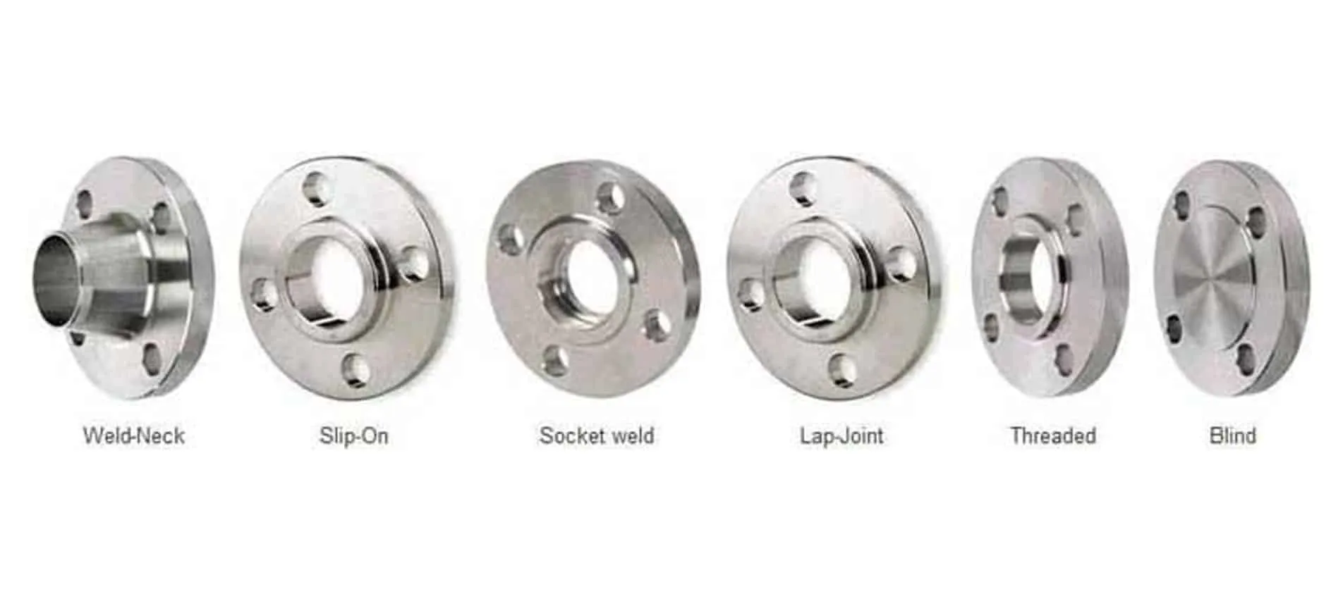
There is no single flange suitable for every piping application. Different pipe flange designs exist because piping systems have different pressure, temperature, accessibility, welding, corrosion, and maintenance requirements. The most commonly encountered types include Weld Neck Flanges, Slip-On Flanges, Blind Flanges, Socket Weld Flanges, Threaded Flanges, and Lap Joint Flanges. Each design connects to the piping system differently and offers a different balance between strength, installation requirements, cost, and service suitability. ASME B16.5 covers several of these flange configurations and establishes dimensional and pressure-temperature requirements for standardized flange designs. (ASME) Choosing a flange should therefore never be based simply on appearance or price. A flange that works perfectly in a low-pressure utility line may be inappropriate for a high-pressure process line. The correct selection starts with understanding what each flange type is designed to do.
Weld Neck Flanges
Weld Neck Flanges are widely associated with demanding industrial piping applications because they use a long, tapered hub and are connected to the pipe using a butt weld. The tapered design provides a gradual transition between the pipe and flange, helping the connection handle mechanical stresses and thermal effects more effectively than simpler flange configurations. This makes weld neck flanges a common choice for applications involving significant pressure, temperature, cyclic loading, or critical process service. They are frequently encountered in refineries, petrochemical plants, chemical plants, power plants, and process equipment installations where reliability is a major consideration. A weld neck flange is generally more expensive and requires qualified welding and inspection procedures, but its robust configuration can make it worthwhile when the service conditions demand additional performance. The flange bore can also be matched appropriately with the pipe to support a smooth flow path. When selecting a weld neck flange, engineers need to consider the pipe size, wall thickness, material grade, pressure class, flange facing, welding requirements, and applicable project specifications. It is not simply a matter of choosing a Pipe flange with the same nominal pipe size. The complete connection must be engineered to suit the service.
Slip-On Flanges
Slip-On Flanges are designed to slide over the outside of a pipe before being welded in position. Their installation is generally simpler than that of weld neck flanges, which can make them attractive for various general-purpose piping applications. The pipe is inserted through the flange and welds are typically made to secure the flange. Because the design does not use the long tapered hub found on a weld neck flange, slip-on flanges are often selected where the operating conditions are less demanding and installation simplicity or cost is important. They can be found in utility piping, water systems, process services, and numerous industrial applications. However, the apparent simplicity should not lead buyers to assume that any slip-on flange will work for any service. Pressure class, temperature, material, gasket type, flange face, welding procedure, and project specifications still matter. A pipe flange should always be selected according to the applicable engineering standard and design conditions rather than purely on convenience. ASME B16.5 provides standardized dimensions and ratings for relevant Pipe flange configurations within its covered size and class ranges. (ASME)
Blind Flanges
A Blind Flange is different because it does not have a central bore through which fluid can flow. Instead, it is essentially a solid flange used to close the end of a pipe, nozzle, valve, or equipment connection. Blind flanges are extremely useful when a piping section needs to be isolated, temporarily closed, or designed for future expansion. For example, a plant may install a blind flange on a branch connection that is expected to be used during a future expansion project. Blind flanges can also be used during maintenance and isolation activities, subject to the applicable safety procedures and engineering requirements. Because there is no pipe opening through the flange, the blind flange must withstand the forces generated by internal pressure. This makes its thickness, material, pressure class, bolt pattern, gasket selection, and installation particularly important. ASME B16.5 includes blind flanges within its scope and provides standardized requirements for applicable sizes and pressure classes. (ASME)
Socket Weld Flanges
Socket Weld Flanges are commonly used in smaller-diameter piping where a pipe is inserted into a socket in the flange and welded around the outside. The design provides a relatively compact connection and can be useful for applications requiring a strong connection without using a butt-welded weld neck configuration. Socket weld flanges are often associated with small-bore industrial piping and higher-pressure applications where threaded connections may not be desirable. However, the detailed application needs to be evaluated because the internal geometry of a socket connection can create considerations related to corrosion, fatigue, and fluid service. Proper installation is essential, including correct fit-up, welding procedure, and inspection. Like other flange types, socket weld flanges are not selected solely by nominal size. The pressure class, material, temperature, fluid, piping specification, and applicable standard must all be considered. For buyers sourcing industrial flanges, providing the complete technical specification to the supplier is much safer than simply asking for a “socket flange.”
Threaded Flanges
Threaded Flanges connect to pipes using internal threads rather than requiring the flange to be welded directly to the pipe. This makes them useful in situations where welding is undesirable or impractical, although their suitability depends heavily on the pressure, temperature, fluid, and project requirements. Threaded connections can be convenient for certain installations because they avoid welding-related operations, but they should not automatically be treated as the universal alternative to welded flanges. The thread specification itself matters, and common systems can include NPT, BSPT, and BSPP, depending on the application and regional requirements. Thread compatibility must be verified before installation because different thread standards are not necessarily interchangeable. Threaded flanges are often used in smaller-diameter piping and selected utility or industrial services. For critical applications, engineers should always verify the applicable piping code and project specification before choosing a threaded connection.
Lap Joint Flanges
Lap Joint Flanges are used with a separate stub end, which is welded to the pipe. Unlike a conventional fixed flange, the lap joint flange can rotate around the stub end, providing useful flexibility during assembly and bolt-hole alignment. This can be particularly convenient in piping systems that require frequent dismantling or where alignment during installation could otherwise be difficult. Another important advantage is that the flange itself does not need to contact the process fluid in the same way as the wetted stub end, allowing the engineer to consider material selection strategically. Lap joint configurations can therefore be attractive in certain corrosive services where the stub end is manufactured from a more corrosion-resistant alloy while the backing flange uses a different material, subject to engineering requirements. Their usefulness becomes especially apparent in systems where maintenance and repeated disassembly are expected. Like every other flange type, however, the complete connection must be evaluated for pressure, temperature, material compatibility, gasket requirements, and applicable standards.
Pipe Flange Types at a Glance
| Pipe Flange Type | Typical Connection | Common Advantage | Typical Consideration |
|---|---|---|---|
| Weld Neck | Butt welded | High mechanical strength | Higher fabrication cost and welding requirements |
| Slip-On | Welded over pipe | Simple installation | Less robust than weld neck for demanding service |
| Blind | Bolted closure | Closes pipe or equipment openings | Must withstand internal pressure |
| Socket Weld | Socket + weld | Compact small-bore connection | Application-specific corrosion/fatigue considerations |
| Threaded | Threaded pipe connection | No direct flange welding | Thread and service compatibility |
| Lap Joint | Stub end + backing flange | Easy alignment and dismantling | Requires compatible stub-end arrangement |
What Are Flange Pressure Classes?
One of the most misunderstood subjects for beginners is flange pressure class. You may see specifications such as Class 150, Class 300, Class 600, Class 900, Class 1500, or Class 2500, but these numbers should not simply be interpreted as the maximum pressure in psi at every temperature. The actual allowable pressure depends on factors including material and temperature, and the applicable standard provides pressure-temperature rating information. ASME B16.5 currently covers flange Class 150, 300, 400, 600, 900, and 1500 for NPS 1/2 through NPS 24, while Class 2500 is covered for NPS 1/2 through NPS 12. (ASME) This distinction is critical when specifying industrial flanges. For example, selecting a Class 600 flange does not mean that every Class 600 flange can safely operate at 600 psi regardless of temperature or material. Engineers must consult the relevant pressure-temperature tables and consider the material grade and operating conditions. This is one reason why a proper flange inquiry should include the size, pressure class, material, temperature, standard, facing, and application instead of simply asking for a “high-pressure flange.”
What Materials Are Pipe Flanges Made From?
Pipe Flanges are manufactured from a wide range of materials because industrial piping systems handle very different environments. Carbon steel, stainless steel, alloy steel, nickel alloys, duplex stainless steel, and other specialty alloys may be selected depending on the operating conditions. Carbon steel can be suitable for many conventional services, while stainless steel may be selected when corrosion resistance is more important. In more aggressive environments, engineers may consider nickel-based alloys or specialized corrosion-resistant materials. Material selection depends on factors such as process fluid, chloride exposure, temperature, pressure, corrosion mechanism, mechanical requirements, welding considerations, and applicable material standards. For example, a Pipe flange intended for a chemical process containing highly corrosive media should not be selected simply because its dimensions match the pipe. The metallurgy is equally important. Material certificates and traceability can also become important requirements for critical industrial projects. Buyers may therefore encounter specifications referencing ASTM, ASME, EN, DIN, JIS, or other standards depending on the project. The correct material is ultimately the one that satisfies the engineering specification and service environment, not necessarily the cheapest available option.
What Are Flange Faces?
The Pipe flange face is the surface that interfaces with the gasket and mating flange to form the sealing area. Different face configurations are available because different applications require different sealing arrangements. Common configurations include Raised Face (RF), Flat Face (FF), and Ring Type Joint (RTJ), with additional specialized facing arrangements used in particular applications. The face selection must be compatible with the mating flange and gasket. A mismatch can compromise the sealing system even when the flange dimensions themselves appear correct. For example, an RTJ connection is designed around a specific ring-type sealing arrangement and should not simply be treated as interchangeable with an ordinary raised-face gasket connection. Surface finish can also matter because gasket performance depends partly on how the mating surfaces interact with the gasket material. For industrial buyers, the flange face should therefore be included in the purchase specification. Saying “ASME B16.5 Class 300 stainless steel flange” may still leave important details unanswered if the facing requirement is not defined.
How Do You Choose the Right Pipe Flange?
Selecting a pipe flange becomes much easier when you stop thinking about the flange as an isolated component and instead consider the complete piping system. Start with the nominal pipe size, then establish the required pressure-temperature rating based on the actual design conditions. Next, determine the material grade based on corrosion resistance, temperature, mechanical properties, and the applicable piping specification. The Pipe flange type should then be selected according to how the component connects to the pipe and what service conditions it will experience. The flange facing and gasket must be compatible, and the bolting specification should also be checked. Finally, verify the governing standard and any project-specific requirements for inspection, testing, marking, documentation, and traceability. ASME B16.5 is particularly important for many industrial Pipe flange applications because it covers dimensions, tolerances, ratings, materials, marking, testing, and requirements related to bolting and gaskets. (ASME) A good purchase specification might therefore identify the product as something like ASME B16.5, NPS 4, Class 300, ASTM A182 F316L, Raised Face, Weld Neck Flange, subject to the actual project requirements. Providing this level of information helps suppliers quote the correct product and reduces the risk of receiving an incompatible flange.
Pipe Flange Standards You Should Know
Industrial Pipe flanges are manufactured according to recognized standards so that dimensions, ratings, materials, and connection details can be consistently specified. ASME B16.5 is one of the most important standards for pipe flanges and flanged fittings and covers NPS 1/2 through NPS 24 within its stated scope. It addresses pressure-temperature ratings, materials, dimensions, tolerances, marking, testing, opening designations, and requirements or recommendations concerning bolting, gaskets, and flange joints.For larger-diameter steel flanges, other standards may apply, including ASME B16.47. Depending on the project and geographic market, buyers may also encounter EN, DIN, JIS, BS, and other national or international standards. These standards should not be mixed casually because dimensions, bolt patterns, pressure designations, and facing details may differ. A flange manufactured to one dimensional standard may not be directly compatible with a Pipe flange manufactured to another standard even if the nominal pipe size appears similar. That is why professional procurement starts with the required standard rather than selecting a flange based only on photographs or nominal dimensions.
Why Are Flanges Important in Industrial Piping?
The real value of a flange becomes obvious when a plant needs to operate, maintain, modify, and expand a piping system over many years. A welded pipe joint can provide a permanent connection, but industrial facilities contain equipment that eventually needs inspection, repair, replacement, cleaning, or modification. Flanged connections provide controlled points where components can be separated without cutting the pipe. This is especially valuable around pumps, valves, heat exchangers, pressure vessels, filters, strainers, tanks, and other process equipment. In a large plant, maintenance teams may need to remove equipment during planned shutdowns, and properly engineered Pipe flange connections make this work more manageable. Flanges can also support modular construction, allowing piping assemblies and equipment to be fabricated, transported, installed, and connected at the project site. However, convenience does not mean that flange connections are maintenance-free. Incorrect bolt tightening, damaged sealing surfaces, poor alignment, wrong gasket selection, corrosion, and improper installation can all contribute to leakage. A reliable flanged system therefore depends on the quality of the flange, gasket, bolts, installation procedure, inspection, and maintenance practices working together.
Pipe Flanges in Oil, Gas, Chemical and Process Industries
The process industries rely heavily on standardized piping components because their systems may transport hydrocarbons, chemicals, steam, water, gases, acids, solvents, and other process media under demanding conditions. In an oil and gas refinery, for example, flanges may connect sections of process piping to valves, pumps, heat exchangers, vessels, and other equipment. In chemical plants, corrosion resistance and material compatibility may become major factors in flange selection. In power plants, temperature and pressure can strongly influence the selection of materials and pressure classes. Fertilizer and petrochemical facilities can introduce additional concerns involving aggressive chemicals, elevated temperatures, and continuous operation. This explains why industrial flange requirements can be much more detailed than ordinary plumbing requirements. The buyer may need to specify the exact standard, material grade, size, class, facing, gasket, bolting, testing, documentation, and inspection requirements. A supplier serving these industries therefore needs to understand not just what a Pipe flange looks like, but how it fits into the complete engineering specification. For companies sourcing industrial flanges and fittings from India, technical communication and documentation can be just as important as price.
How to Buy Pipe Flanges From a Reliable Supplier
When purchasing pipe flanges, the safest approach is to provide a complete technical requirement instead of sending only a product name. Start by stating the flange type, nominal size, pressure class, material grade, applicable standard, facing, quantity, and delivery requirement. If the project has special requirements such as NACE compliance, PMI, third-party inspection, EN 10204 documentation, radiography, heat treatment, or material traceability, those should also be communicated before quotation. A professional supplier should be able to review the specification and identify missing information before manufacturing or supplying the product. Jade Special Metals’ online product information, for example, identifies the company as serving industrial customers with piping-related products and provides technical specifications on its product pages. (Flanges Fitting) For international buyers, the inquiry should also clarify whether the Pipe flange is required for a specific project standard or client-approved vendor list. This helps avoid a common procurement mistake: selecting a Pipe flange that looks correct dimensionally but does not satisfy the project’s material, pressure, documentation, or inspection requirements. A good supplier relationship is not simply about obtaining the lowest price; it is about obtaining the right component with the right documentation at the right time.
Common Pipe Flange Selection Mistakes
Beginners often make the mistake of selecting a flange based on only one specification, such as pipe diameter or pressure class. A 4-inch flange, for example, still requires decisions about flange type, material, class, facing, standard, and connection method. Another common mistake is assuming that pressure class numbers represent a universal pressure limit at all temperatures. They do not; pressure-temperature ratings need to be evaluated according to the applicable standard and material. Buyers can also overlook gasket compatibility or assume that any flange with the same nominal size will mate correctly. Mixing standards without checking dimensions and bolt patterns can create serious installation problems. Material substitution is another concern, particularly when a project specifies a corrosion-resistant alloy or a particular ASTM/ASME grade. Finally, some buyers focus entirely on the initial purchase price while overlooking documentation, inspection, material traceability, machining quality, delivery reliability, and long-term service requirements. In industrial piping, a small saving on a flange can become expensive if the wrong component causes installation delays or leakage. The smarter approach is to evaluate the total technical and commercial suitability of the flange before placing an order.
Pipe Flange Maintenance and Inspection
Even a properly manufactured flange needs appropriate handling and maintenance after it arrives at the site. Before installation, flange faces should be inspected for damage, corrosion, dents, contamination, or scratches that could affect sealing. The gasket should be correct for the flange face, process fluid, temperature, and pressure, and it should be installed according to the applicable procedure. Bolting should be checked for suitability and installed using an appropriate tightening sequence and method. Misalignment should not simply be corrected by forcing the flanges together with excessive bolt load because this can introduce unwanted stresses into the piping system. During operation, maintenance teams should watch for signs of leakage, corrosion, vibration, or unusual joint movement. During shutdowns, flange surfaces, bolts, gaskets, and adjacent piping can be inspected as part of the maintenance program. These practices may seem basic, but they are exactly the details that determine whether a flange remains a dependable connection throughout its service life. The goal is not merely to install a Pipe flange; the goal is to maintain a safe, leak-resistant and mechanically reliable piping joint.
Final Thoughts : Understanding Pipe Flanges Made Simple
A pipe flange is a mechanical connection component that allows pipes, valves, equipment, and other piping components to be joined in a strong and detachable manner. The basic concept is simple: two mating flange faces are held together with bolts while a gasket creates the sealing barrier. The engineering behind that simple connection, however, can become highly sophisticated when the system operates at high pressure, high temperature, or in corrosive environments. Understanding the major flange types—including weld neck, slip-on, blind, socket weld, threaded, and lap joint flanges—makes it much easier to understand why different designs exist. Pressure class, material, flange facing, dimensions, gasket compatibility, bolting, and applicable standards must all be considered before selecting a flange. ASME B16.5 remains a key reference for many standardized pipe flange and flanged fitting applications, covering NPS 1/2 through NPS 24 and a range of pressure classes within its scope. For buyers and engineers, the most important lesson is simple: never select a flange by size alone. Define the complete service requirement, verify the applicable standard, and work with a supplier capable of providing the required material, dimensions, quality, documentation, and technical support. For industrial piping requirements, Jade Special Metals can be positioned as a source for flanges, fittings, and related piping products through its online presence at flangesfitting.com.
Frequently Asked Questions About Pipe Flanges
1. What is a pipe flange used for?
A pipe flange is used to create a detachable connection between pipes, valves, fittings, equipment nozzles, and other components in a piping system. It normally works together with a gasket and bolting to create a sealed mechanical joint. Flanges are particularly useful where equipment may need to be removed, inspected, repaired, or replaced.
2. What are the most common types of pipe flanges?
The most common industrial types include weld neck, slip-on, blind, socket weld, threaded, and lap joint flanges. The correct type depends on the piping design, pressure, temperature, material, welding requirements, maintenance needs, and applicable standard.
3. What does Class 150 or Class 300 mean on a flange?
Flange classes such as 150, 300, 600, 900, 1500, and 2500 are standardized pressure-rating designations, but they should not be interpreted as a simple maximum pressure in psi at every temperature. Actual pressure-temperature ratings depend on the applicable standard and material. ASME B16.5 provides the relevant rating framework for the flange sizes and classes within its scope. (ASME)
4. Which material is best for pipe flanges?
There is no single best flange material for every application. Carbon steel, stainless steel, alloy steel, duplex stainless steel, and nickel alloys may all be appropriate depending on the process fluid, pressure, temperature, corrosion environment, mechanical requirements, and project specification. Material selection should always follow the applicable engineering requirements.
5. How do I specify a pipe flange when requesting a quotation?
Provide as much technical information as possible, including flange type, nominal pipe size, pressure class, material grade, standard, flange facing, quantity, and application. If required, also specify inspection, testing, material certificates, traceability, NACE requirements, third-party inspection, and delivery requirements. A complete specification helps the supplier quote the correct flange rather than making assumptions